Optical Distance Sensor
Op-amp filters & photonics · UBC Mech 368
- Project year
- 2025
- Status
- Completed
A photodiode-based distance sensor with a photoamplifier, active filters and rectifier, read by an Arduino and verified with FFT analysis in MATLAB.
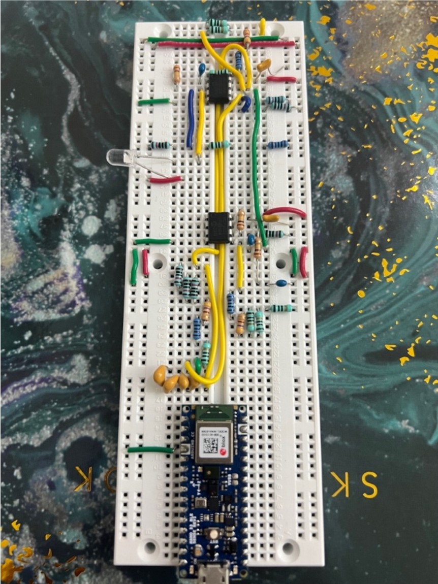
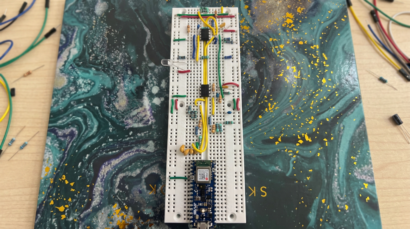
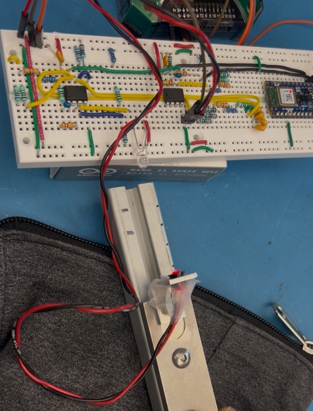
This project — from UBC's Mech 368 instrumentation course — involved designing an optical distance sensor from a photodiode and a modulated LED. A chain of analog stages built from MCP6002 op-amps — a photoamplifier, high-pass filter, band-pass amplifier, rectifier and low-pass filter — converted a 1 kHz modulated optical signal into a clean DC voltage proportional to distance, rejecting ambient light noise.
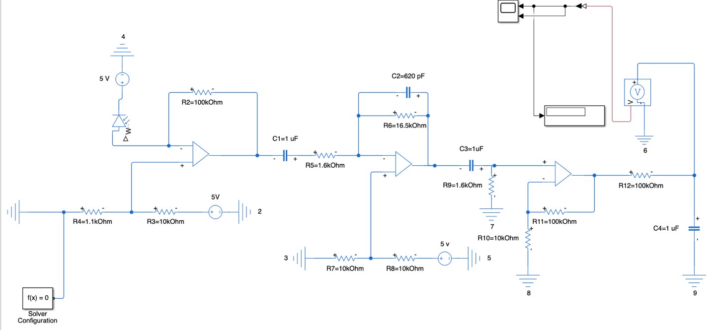
Signal conditioning — The photodiode amplifier operating point was set with a voltage divider, and a 100 Hz high-pass filter removed ambient light drift so only the LED's 1 kHz modulation remained. The band-pass stage amplified the signal without saturation, and the rectifier plus low-pass filter produced a stable DC output that varied predictably with distance.
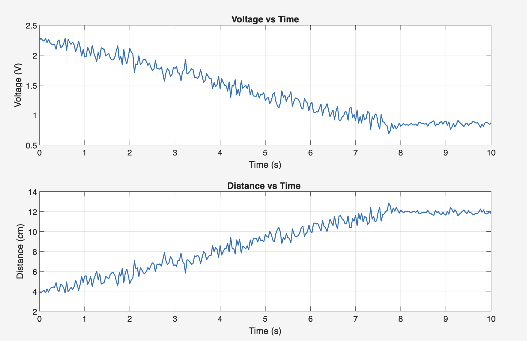
Calibration and readout — Calibration against known distances produced the linear equation Distance = −4.2671 × Voltage + 12.8666 (cm), valid over the 4–12 cm range. An Arduino read the voltage, and MATLAB code converted it to real-time distance with out-of-range detection for targets too close or too far.
Verification — The full circuit was modelled in MATLAB/Simulink and validated stage-by-stage against reference waveforms using an AD2 oscilloscope. Fourier analysis of the photodiode signal confirmed the LED flashing frequency, with the FFT showing a clear dominant peak at the chosen 10 Hz rate.